CABLE CONCENTRICO CU Y AL
Cables para Acometidas Antifraudes
Cables antifraude acometida concéntrica ARE/APE
Manufacturer & Supplier from China
Send email for price list
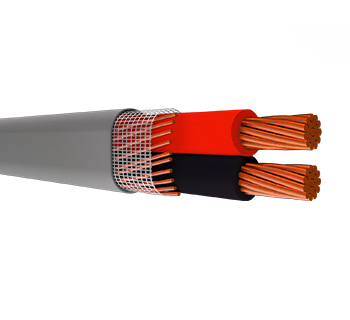
Service Entrance Type SEU & SER
Service Entrance Cable Unarmored or U-shaped
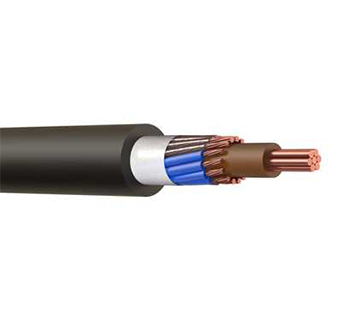
Service Entrance Cable Round
Description
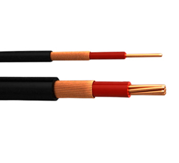
Service Entrance SEU: one or two XHHW-2 insulated conductors, paralleled, with concentric neutral, reinforced tape and PVC jacket. Service Entrance SER: two or three XHHW-2 insulated conductors, twisted together with or without bare grounding conductor, reinforced tape and PVC jacket.
Construction
Conductor Soft copper stranded and compressed. Insulation Cross Linked Polyethylene (XLPE 90°C).
Design
Service Entrance Type U, SEU: Round configuration for one phase conductor and neutral, flan configuration for two phase conductors and neutral.
Neutral
Service Entrance SEU : soft copper wires applied concentrically around phases with SZ technology (UL 854 Section 15.4)
Service Entrance SER: soft copper stranded, twisted together with phases
Binder
Tape Service Entrance SEU: polyester tape over neutral conductor Service Entrance SER: polyester tape over assembly
Jacket
Flame Retardant and Sunlight resistant PVC.
Options THWN-2 Conductors. Jacket with PVC LS (LOW Smoke emission).
Aluminum conductors.
Characteristics
Operating Temperature Dry and wet locations 90°C.
Operating Voltage 600 V.
Uses and Applications
Service Entrance or Drop Cable up to Service Entrance Equipment and to general breaker. May be used for branch circuits according to NEC and NTC 2050.
Standards and Specifications
Service Entrance Cables are manufactured under the following standards:
ASTM B3, NTC-359. Soft copper wires.
ASTM B8, NTC-307. Concentric Lay Stranded copper conductors. ASTM B787. 19 Wire Combination Unilay Stranded Copper conductors for subsequent insulation
UL 1581, NTC-3203. Reference Standard for Electrical Wires, Cables and Flexible Cords.
UL 854, NTC-ICONTEC 4564. Service Entrance Cables.
Service Entrance Type ARE & APE
A: Service Entrance R: Round Configuration E: Concentric Neutral Conductor
A: Service Entrance P: Flat Configuration E: Concentric Neutral Conductor
Description
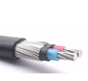
ARE: one or two XLPE insulated conductors, twisted together, with concentric
neutral, PVC filler and PE jacket.
APE: two XLPE insulated conductors, paralleled, with polyester tape, concentric
neutral, and PE jacket.
Service Entrance SER: two or three XHHW-2 insulated conductors, twisted
together with or without bare grounding conductor, reinforced tape and PVC
jacket.
Construction
Conductor: Soft copper stranded and compressed.
Insulation: Cross Linked Polyethylene (XLPE 90°C).
Configuration: ARE: Round. APE: Flat.
Binder Tape: APE: Polyester Tape over paralleled conductors.
Neutral: Soft copper wires applied concentrically around phases with SZ technology
with high coverage over phase conductors.
Jacket: Polyethylene (PE). Rip cord for easy installation.
Options: Aluminum conductor. PVC Insulation. Sunlight Resistant PVC Jacket.
Low Smoke Emission PVC Jacket.
Characteristics
Operation Temperature: Dry and wet locations 90°C.
Operating Voltage: 600 V.
Uses and Applications
Service Entrance or Drop Cable up to Service Entrance Equipment and to general breaker
Standards
ARE and APE Service Entrance Cables are manufactured under the following standards:
ASTM B3, NTC-359. Soft copper wires.
ASTM B8, NTC-307. Concentric Lay Stranded copper conductors.
Service Entrance Type SEU 600V (International System Unit)
Service Entrance Cable Unarmored or U-shaped
Manufacturing Standard: UL 854, NTC 4564. Service Entrance Cables
CODE | SIZE AWG | STRANDS No. | STRANDING CLASS | CROSS SECTION | CONDUCTOR DIAMETER | INSULATION THICKNESS | DIAMETER OVER INSULATION | NEUTRAL SIZE AWG | NEUTRAL CONDUCTOR | POLYE STERICTAPE THICKNESS | JACKE TTHICKNESS | DIMENSIONS OVER JACKET | APPROX. TOTAL WEIGHT | DC RESISTANCE AT 20°C1 | AMPACITY 2 | |
(mm2) | (mm) | (mm) | (mm) | STRANDSNo. | STRANDDIAMETER(mm) | (mm) | (mm) | (mm) | (kg/km) | (ohm/km) | (A) | |||||
1 x 10 + 10 | 10 | 1 | SOLID | 5.26 | 2.59 | 0.76 | 4.18 | 10 | 26 | 0.51 | 0.032 | 0.76 | 6.82 | 126 | 3.28 | 40 |
1 x 8 + 8 | 8 | 7 | B | 8.37 | 3.59 | 1.14 | 5.96 | 8 | 41 | 0.51 | 0.032 | 1.14 | 9.36 | 216 | 2.1 | 55 |
1 x 6 + 6 | 6 | 7 | B | 13.3 | 4.52 | 1.14 | 6.89 | 6 | 41 | 0.64 | 0.032 | 1.14 | 10.56 | 316 | 1.32 | 75 |
1 x 4 + 4 | 4 | 7 | B | 21.15 | 5.71 | 1.14 | 8.08 | 4 | 41 | 0.81 | 0.032 | 1.14 | 12.08 | 475 | 0.831 | 95 |
1 x 2 + 2 | 2 | 7 | B | 33.63 | 7.2 | 1.14 | 9.57 | 2 | 41 | 1.02 | 0.032 | 1.14 | 13.99 | 721 | 0.523 | 130 |
2 x 10 + 10 | 10 | 1 | SOLID | 5.26 | 2.59 | 0.76 | 4.18 | 10 | 26 | 0.51 | 0.032 | 0.76 | 6.90 x 11.08 | 195 | 3.28 | 40 |
2 x 8 + 8 | 8 | 7 | B | 8.37 | 3.59 | 1.14 | 5.96 | 8 | 41 | 0.51 | 0.032 | 1.14 | 9.45 x 15.42 | 338 | 2.1 | 55 |
2 x 6 + 6 | 6 | 7 | B | 13.3 | 4.52 | 1.14 | 6.89 | 6 | 41 | 0.64 | 0.032 | 1.14 | 10.65 x 17.54 | 492 | 1.32 | 75 |
2 x 4 + 4 | 4 | 7 | B | 21.15 | 5.71 | 1.14 | 8.08 | 4 | 41 | 0.81 | 0.032 | 1.14 | 12.17 x 20.25 | 733 | 0.831 | 95 |
2 x 2 + 2 | 2 | 7 | B | 33.63 | 7.2 | 1.14 | 9.57 | 2 | 41 | 1.02 | 0.032 | 1.14 | 14.09 x 23.66 | 1107 | 0.523 | 130 |
2 x 8 + 10 | 8 | 7 | B | 8.37 | 3.59 | 1.14 | 5.96 | 10 | 26 | 0.51 | 0.032 | 1.14 | 9.45 x 15.42 | 309 | 2.1 | 55 |
2 x 6 + 8 | 6 | 7 | B | 13.3 | 4.52 | 1.14 | 6.89 | 8 | 41 | 0.51 | 0.032 | 1.14 | 10.38 x 17.28 | 445 | 1.32 | 75 |
2 x 4 + 6 | 4 | 7 | B | 21.15 | 5.71 | 1.14 | 8.08 | 6 | 41 | 0.64 | 0.032 | 1.14 | 11.83 x 19.91 | 657 | 0.831 | 95 |
2 x 2 + 4 | 2 | 7 | B | 33.63 | 7.2 | 1.14 | 9.57 | 4 | 41 | 0.81 | 0.032 | 1.14 | 13.66 x 23.23 | 989 | 0.523 | 130 |
Service Entrance Type SER 600V (International System Unit)
Service Entrance Cable Round
Manufacturing Standard: UL 854, NTC 4564. Service Entrance Cables
CODE | SIZE AWG | STRANDS No. | STRANDING CLASS | CROSS SECTION | CONDUCTOR DIAMETER | INSULATION THICKNESS | DIAMETER OVER INSULATION | NEUTRAL SIZE AWG | NEUTRAL CONDUCTOR STRANDS No. | NEUTRAL CONDUCTOR DIAMETER No. | ASSEMBLY DIAMETER | REINFOR CEDTAPE THICKNESS | JACKET THICKNESS | DIMENSIONS OVER JACKET | APPROX. TOTAL WEIGHT | DC RESISTANCE AT 20°C1 | AMPACITY 2 |
(mm2) | (mm) | (mm) | (mm) | (mm) | (mm) | (mm) | (mm) | (kg/km) | (ohm/km) | (A) | |||||||
3 x 8 | 8 | 7 | B | 8.37 | 3.59 | 1.14 | 5.96 | - | - | - | 12.85 | 0.1 | 0.76 | 14.75 | 344 | 2.12 | 55 |
3 x 6 | 6 | 7 | B | 13.3 | 4.52 | 1.14 | 6.89 | - | - | - | 14.86 | 0.1 | 0.76 | 16.75 | 501 | 1.34 | 75 |
3 x 4 | 4 | 7 | B | 21.15 | 5.71 | 1.14 | 8.08 | - | - | - | 17.41 | 0.1 | 0.76 | 19.3 | 744 | 0.84 | 95 |
3 x 2 | 2 | 7 | B | 33.63 | 7.2 | 1.14 | 9.57 | - | - | - | 20.62 | 0.1 | 0.76 | 22.52 | 1124 | 0.528 | 130 |
3 x 1 | 1 | 19 | B | 42.41 | 8.18 | 1.4 | 11.09 | - | - | - | 23.9 | 0.1 | 0.76 | 25.8 | 1411 | 0.419 | 150 |
3 x 1/0 | 1/0 | 19 | B | 53.48 | 9.18 | 1.4 | 12.09 | - | - | - | 26.05 | 0.1 | 0.76 | 27.95 | 1740 | 0.332 | 170 |
3 x 2/0 | 2/0 | 19 | B | 67.43 | 10.31 | 1.4 | 13.22 | - | - | - | 28.5 | 0.1 | 0.76 | 30.39 | 2153 | 0.263 | 195 |
3 x 3/0 | 3/0 | 19 | B | 85.03 | 11.58 | 1.4 | 14.49 | - | - | - | 31.23 | 0.1 | 0.76 | 33.13 | 2669 | 0.209 | 225 |
3 x 4/0 | 4/0 | 19 | B | 107.2 | 13 | 1.4 | 15.91 | - | - | - | 34.28 | 0.1 | 0.76 | 36.18 | 3317 | 0.166 | 260 |
3 x 8 + 8 | 8 | 7 | B | 8.37 | 3.59 | 1.14 | 5.96 | 8 | 7 | 3.59 | 13.72 | 0.1 | 0.76 | 15.61 | 424 | 2.12 | 55 |
3 x 6 + 6 | 6 | 7 | B | 13.3 | 4.52 | 1.14 | 6.89 | 6 | 7 | 4.52 | 15.86 | 0.1 | 0.76 | 17.75 | 626 | 1.34 | 75 |
3 x 4 + 6 | 4 | 7 | B | 21.15 | 5.71 | 1.14 | 8.08 | 6 | 7 | 4.52 | 18.58 | 0.1 | 0.76 | 20.47 | 870 | 0.84 | 95 |
3 x 2 + 4 | 2 | 7 | B | 33.63 | 7.2 | 1.14 | 9.57 | 4 | 7 | 5.71 | 22.01 | 0.1 | 0.76 | 23.91 | 1323 | 0.528 | 130 |
3 x 1/0 + 2 | 1/0 | 19 | B | 53.48 | 9.18 | 1.4 | 12.09 | 2 | 7 | 7.2 | 27.81 | 0.1 | 0.76 | 29.7 | 2055 | 0.332 | 170 |
3 x 2/0 + 1 | 2/0 | 19 | B | 67.43 | 10.31 | 1.4 | 13.22 | 1 | 19 | 8.18 | 30.41 | 0.1 | 0.76 | 32.31 | 2548 | 0.263 | 195 |
3 x 3/0 + 1/0 | 3/0 | 19 | B | 85.03 | 11.58 | 1.4 | 14.49 | 1/0 | 19 | 9.18 | 33.33 | 0.1 | 0.76 | 35.23 | 3167 | 0.209 | 225 |
3 x 4/0 + 2/0 | 4/0 | 19 | B | 107.2 | 13 | 1.4 | 15.91 | 2/0 | 19 | 10.31 | 36.59 | 0.1 | 0.76 | 38.49 | 3943 | 0.166 | 260 |
Service Entrance Type ARE 600V (International System Unit)
A: Service Entrance R: Round Configuration E: Concentric Neutral Conductor
Standard: ICEA S-95-658, NTC-ICONTEC 1099-1. Power Cables rated 2000 volts or less for the Distribution of Electrical Energy
CODE | SIZE AWG | STRANDS No. | STRANDING CLASS | CROSS SECTION | CONDUCTOR DIAMETER | INSULATION THICKNESS | DIAMETER OVER INSULATION | FILLER THICKNESS | DIAMETER | NEUTRAL | NEUTRAL CONDUCTOR | JACKET THICKNESS | DIMENSIONS OVER JACKET | APPROX. TOTAL WEIGHT | DC RESISTANCE AT 20°C1 | AMPACITY 2 | |
(mm2) | (mm) | (mm) | (mm) | (mm) | (mm) | STRANDS | STRAND | (mm) | (mm) | (kg/km) | (ohm/km) | (A) | |||||
1 x 12 + 12 | 12 | 1 | SOLID | 3.31 | 2.05 | 0.76 | 3.65 | - | 3.65 | 12 | 17 | 0.51 | 1.14 | 7.04 | 88 | 5.21 | 30 |
1 x 10 + 10 | 10 | 1 | SOLID | 5.26 | 2.59 | 0.76 | 4.18 | - | 4.18 | 10 | 26 | 0.51 | 1.14 | 7.58 | 126 | 3.28 | 40 |
1 x 8 + 8 | 8 | 7 | B | 8.37 | 3.59 | 1.14 | 5.96 | - | 5.96 | 8 | 41 | 0.51 | 1.14 | 9.36 | 202 | 2.1 | 55 |
1 x 6 + 8 | 6 | 7 | B | 13.3 | 4.52 | 1.14 | 6.89 | - | 6.89 | 8 | 41 | 0.51 | 1.14 | 10.29 | 254 | 1.32 | 75 |
1 x 4 + 6 | 4 | 7 | B | 21.15 | 5.71 | 1.14 | 8.08 | - | 8.08 | 6 | 41 | 0.64 | 1.14 | 11.73 | 382 | 0.83 | 95 |
1 x 2 + 4 | 2 | 7 | B | 33.63 | 7.2 | 1.14 | 9.57 | - | 9.57 | 4 | 41 | 0.81 | 1.52 | 14.36 | 598 | 0.52 | 130 |
2 x 12 + 12 | 12 | 1 | SOLID | 3.31 | 2.05 | 0.76 | 3.65 | 0.5 | 8.3 | 12 | 26 | 0.51 | 1.14 | 7.04 | 173 | 5.21 | 30 |
2 x 10 + 10 | 10 | 1 | SOLID | 5.26 | 2.59 | 0.76 | 4.18 | 0.5 | 9.37 | 10 | 26 | 0.51 | 1.14 | 7.58 | 243 | 3.28 | 40 |
2 x 8 + 8 | 8 | 7 | B | 8.37 | 3.59 | 1.14 | 5.96 | 0.5 | 12.93 | 8 | 41 | 0.51 | 1.14 | 9.36 | 408 | 2.1 | 55 |
2 x 6 + 8 | 6 | 7 | B | 13.3 | 4.52 | 1.14 | 6.89 | 0.5 | 14.79 | 8 | 41 | 0.51 | 1.14 | 10.29 | 543 | 1.32 | 75 |
2 x 4 + 6 | 4 | 7 | B | 21.15 | 5.71 | 1.14 | 8.08 | 0.5 | 17.15 | 6 | 41 | 0.64 | 1.14 | 11.73 | 794 | 0.831 | 95 |
2 x 2 + 4 | 2 | 7 | B | 33.63 | 7.2 | 1.14 | 9.57 | 0.5 | 20.14 | 4 | 41 | 0.81 | 1.52 | 14.36 | 1200 | 0.523 | 130 |
Service Entrance Type APE 600V (International System Unit)
A: Service Entrance P: Flat Configuration E: Concentric Neutral Conductor
Standard: ICEA S-95-658, NTC-ICONTEC 1099-1.
Power Cables rated 2000 volts or less for the Distribution of Electrical Energy
CODE | SIZE AWG | STRANDS No. | STRANDING CLASS | CROSS SECTION | CONDUCTOR DIAMETER | INSULATION THICKNESS | DIAMETER OVER INSULATION | NEUTRAL SIZE AWG | NEUTRAL CONDUCTOR STRANDS No. | POLYESTERIC | JACKET | DIMENSIONS | APPROX. TOTAL WEIGHT | DC RESISTANCE AT 20°C1 | AMPACITY 2 |
(mm2) | (mm) | (mm) | (mm) | (kg/km) | (ohm/km) | (A) | |||||||||
2 x 10 + 10 | 10 | 1 | SOLID | 5.26 | 2.59 | 0.76 | 4.18 | 10 | 26 | 0.032 | 1.14 | 7.67 x 11.86 | 196 | 3.28 | 40 |
2 x 8 + 8 | 8 | 7 | B | 8.37 | 3.59 | 1.14 | 5.96 | 8 | 41 | 0.032 | 1.14 | 9.45 x 15.42 | 316 | 2.1 | 55 |
2 x 6 + 6 | 6 | 7 | B | 13.3 | 4.52 | 1.14 | 6.89 | 6 | 41 | 0.032 | 1.14 | 10.65 x 17.54 | 467 | 1.32 | 75 |
2 x 4 + 4 | 4 | 7 | B | 21.15 | 5.71 | 1.14 | 8.08 | 4 | 41 | 0.032 | 1.14 | 12.17 x 20.25 | 704 | 0.831 | 95 |
2 x 2 + 2 | 2 | 7 | B | 33.63 | 7.2 | 1.14 | 9.57 | 2 | 41 | 0.032 | 1.14 | 14.09 x 23.66 | 1072 | 0.523 | 130 |
2 x 8 + 10 | 8 | 7 | B | 8.37 | 3.59 | 1.14 | 5.96 | 10 | 26 | 0.032 | 1.14 | 9.45 x 15.42 | 288 | 2.1 | 55 |
2 x 6 + 8 | 6 | 7 | B | 13.3 | 4.52 | 1.14 | 6.89 | 8 | 41 | 0.032 | 1.14 | 10.38 x 17.28 | 420 | 1.32 | 75 |
2 x 4 + 6 | 4 | 7 | B | 21.15 | 5.71 | 1.14 | 8.08 | 6 | 41 | 0.032 | 1.14 | 11.83 x 19.91 | 628 | 0.831 | 95 |
2 x 2 + 4 | 2 | 7 | B | 33.63 | 7.2 | 1.14 | 9.57 | 4 | 41 | 0.032 | 1.14 | 13.66 x 23.23 | 955 | 0.523 | 130 |


 中文
中文