Often used for buried ground grid systems, overhead ground wire and messenger wire
Supplier, Manufacturer, Factory from China
MOQ: 10KM
Application:
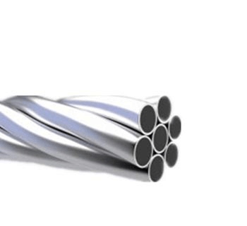
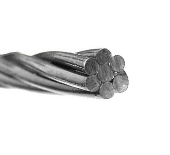
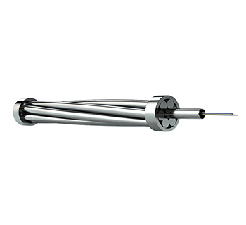
The copper-clad strand wire is shaped like a cable, which is made of a plurality of copper-clad single wires. Because of its multi-stranded properties, the electrical conductivity and tensile strength are relatively good, and the product can be customized to enhance the elongation rate by multiple heat treatment in the production process, which has increased the strength and toughness of the steel compared with the pure copper strand. Moreover, the good electrical conductivity and corrosion resistance of the copper material are maintained due to the principle of the skin effect. Therefore, it is very popular in many fields of lightning protection and grounding, especially in power plants, substations, high-speed rail, subways, electrified railways, large-scale chemical plants, mechanical plants, communication base stations, transportation, computer rooms, highways and military bases.
Characteristics
1.High conductivity (up to 70% and above)
The copper-clad strand wire produced by our company generally has a conductivity of 30%-70%, and more than 70% can be customized according to customer requirements.
2.High tensile strength
The multi-stranded copper-clad strand wire has high tensile strength and can be made into copper-clad steel strand wire with high electrical conductivity and high tensile strength after being enhanced by special treatment process to be suitable for special use occasions.
3.Long life
The copper plating of single-stranded copper-clad round steel (copperweld steel) of multi-stranded copper-clad strand is thick, the excellent production process makes copper layer tightly combined and bent 180-360 degrees without cracking and its life is long and can be more than 30 years.
4.Low cost
The characteristics of high conductivity and corrosion resistance have greatly reduced the number of grounding conductors used in grounding projects, which can significantly save costs and achieve outstanding economic benefits.
5.Convenient construction and transportation
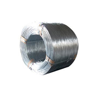
The single length of the copper-clad copperweld strand can be up to 100 meters, because the 100-meter package or the hundred-meter cable can be transported more easily. The welding between the grounding grids during the construction is recommended to use the exothermic welding series products produced by our company. There are different shapes of molds for exothermic welding, so that different permanent joints can be randomly welded. The construction operation is simple and easy to learn, and the various conductors of the grounding grid are welded together to become a true maintenance-free device.

Standards
American Standard&Canadian national standards——ASTM-B227 B228 B901
International Electrotechnical Commission International Standards——IEC
ASTM-B227 B228 B901
Model | Nominal area | Wire quantity | Outer diameter | Weight/km | Pulling strength | 20℃ Max resistance | ||||||
Mono-filament | Conductor | Grade 30 | Grade 40 | Grade 40 LC | Grade 30 LC | Grade 40 HS | Grade 30 HS | Grade 40 | Grade 30 | |||
mm2 | mm | mm | Kg/km | kgf | Ω/km | |||||||
19 No.5 | 318.7 | 19 | 4.62 | 23.11 | 2634 | 2660.8 | 7823 | 8800 | 8800 | 9778 | 0.1442 | 0.1923 |
19 No.6 | 252.7 | 19 | 4.11 | 20.57 | 2087.8 | 2110.2 | 6205 | 6980 | 6980 | 7756 | 0.1818 | 0.2424 |
19 No.7 | 200.45 | 19 | 3.66 | 18.31 | 1656.3 | 1674.1 | 4923 | 5538 | 5538 | 6154 | 0.2294 | 0.3058 |
19 No. 8 | 158.96 | 19 | 3.26 | 16.31 | 1313.6 | 1327.4 | 3904 | 4392 | 4392 | 4880 | 0.289 | 0.3852 |
19 No. 9 | 126.06 | 19 | 2.91 | 14.53 | 1041.7 | 1052.5 | 3094 | 3481 | 3481 | 3868 | 0.3645 | 0.4862 |
7 No. 4 | 148.06 | 7 | 5.19 | 15.57 | 1218.6 | 1231.4 | 3636 | 4090 | 4090 | 4544 | 0.3093 | 0.4124 |
7 No. 5 | 117.41 | 7 | 4.62 | 13.87 | 966.4 | 976.5 | 2882 | 3242 | 3242 | 3603 | 0.3898 | 0.5197 |
7 No. 6 | 93.09 | 7 | 4.11 | 12.34 | 766.2 | 774.2 | 2286 | 2572 | 2572 | 2857 | 0.4915 | 0.6552 |
7 No.7 | 73.87 | 7 | 3.67 | 11 | 608 | 614.4 | 1814 | 2040 | 2040 | 2267 | 0.6201 | 0.8268 |
7 No. 8 | 58.56 | 7 | 3.26 | 9.78 | 482 | 487 | 1438 | 1618 | 1618 | 1798 | 0.7812 | 1.0414 |
7 No. 9 | 46.43 | 7 | 2.9 | 8.71 | 382.1 | 386.1 | 1140 | 1282 | 1282 | 1425 | 0.9859 | 1.3144 |
7 No. 10 | 36.82 | 7 | 2.59 | 7.77 | 303.1 | 306.2 | 904 | 1017 | 1017 | 1131 | 1.2422 | 1.6559 |
3 No. 5 | 50.32 | 3 | 4.62 | 9.96 | 413.4 | 417.7 | 1304 | 1467 | 1467 | 1630 | 0.9082 | 1.2104 |
3 No. 6 | 39.9 | 3 | 4.11 | 8.86 | 327.8 | 331.2 | 1034 | 1163 | 1163 | 1293 | 1.1447 | 1.526 |
3 No. 7 | 31.64 | 3 | 3.66 | 7.9 | 259.9 | 262.6 | 820 | 923 | 923 | 1026 | 1.444 | 1.925 |
3 N0. 8 | 25.09 | 3 | 3.26 | 7.04 | 206.1 | 208.3 | 651 | 732 | 732 | 813 | 1.8193 | 2.4253 |
3 No. 9 | 19.9 | 3 | 2.91 | 6.27 | 163.5 | 165.1 | 516 | 580 | 580 | 645 | 2.2957 | 3.0605 |
3 No. 10 | 15.78 | 3 | 2.59 | 5.59 | 129.6 | 130.9 | 409 | 460 | 460 | 511 | 2.8929 | 3.8552 |
3 No. 12 | 9.92 | 3 | 2.05 | 4.42 | 81.5 | 82.4 | 260 | 292 | 292 | 325 | 4.5573 | 6.0731 |
IEC
Size | Strands*single path | Diameter | Conductivity |
mm2 | mm | % | |
10 | 7*1.4 | 4.2 | 18%—70% |
16 | 7*1.7 | 5.1 | 18%—70% |
25 | 7*2.14 | 6.42 | 18%—70% |
35 | 7*2.52 | 7356 | |
50 | 7*3.00 | 9 | 18%—70% |
70 | 19*1.44 | 10.7 | 18%—70% |
95 | 19*2.52 | 12.6 | 18%—70% |
120 | 19*2.80 | 14 | 18%—70% |
150 | 19*3.15 | 15.75 | 18%—70% |
185 | 37*2.52 | 17.64 | 18%—70% |
240 | 37*2.85 | 19.95 | 18%—70% |
300 | 37*3.15 | 21.7 | 18%—70% |
IEC
Nominal Sectional Area mm2 | structure Stock/diameter mm | Area mm2 | Breaking load kg | D.C.Resistance Ω/km | Line quality Kg/km | ||||
40HS | 30HS | 30EHS | 40% | 30% | 30% | 40% | |||
320 | 19/4.62 | 318.71 | 22788 | 25206 | 30350 | 0.1399 | 0.1865 | 2634.0 | 2660.8 |
250 | 19/4.12 | 252.71 | 18849 | 20788 | 25188 | 0.1764 | 0.2352 | 2087.9 | 2110.2 |
200 | 19/3.67 | 200.45 | 15599 | 17118 | 20797 | 0.2225 | 0.2966 | 1656.3 | 1674.2 |
160 | 19/3.26 | 158.97 | 12873 | 14079 | 17096 | 0.2805 | 0.3740 | 1313.6 | 1327.2 |
120 | 19/2.91 | 126.06 | 10609 | 11567 | 13884 | 0.3537 | 0.4715 | 1041.7 | 1052.6 |
150 | 7/5.19 | 148.06 | 10120 | 11240 | 13349 | 0.3000 | 0.4000 | 1218.7 | 1231.5 |
120 | 7/4.62 | 117.42 | 8396 | 9285 | 11181 | 0.3783 | 0.5043 | 966.41 | 976.53 |
90 | 7/4.12 | 93.097 | 6954 | 7661 | 9280 | 0.4771 | 0.6359 | 766.25 | 774.29 |
70 | 7/3.67 | 73.871 | 5747 | 6309 | 7661 | 0.6014 | 0.8019 | 608.06 | 614.46 |
60 | 7/3.26 | 58.561 | 4745 | 5189 | 6300 | 0.7586 | 1.0109 | 482.02 | 487.07 |
50 | 7/2.91 | 46.439 | 3908 | 4261 | 5116 | 0.9564 | 1.2750 | 382.16 | 386.18 |
35 | 7/2.59 | 36.826 | 3230 | 3519 | 4171 | 1.2061 | 1.6077 | 303.14 | 306.26 |
50 | 3/4.62 | 50.322 | 3798 | 4201 | 5380 | 0.8809 | 1.1743 | 413.41 | 417.73 |
40 | 3/4.12 | 39.903 | 3145 | 3465 | 4424 | 1.1106 | 1.4807 | 327.84 | 331.26 |
30 | 3/3.67 | 31.645 | 2600 | 2854 | 3593 | 1.4007 | 1.8672 | 259.98 | 262.66 |
25 | 3/3.26 | 25.097 | 2145 | 2347 | 2849 | 1.7662 | 2.3544 | 206.11 | 208.34 |
20 | 3/2.91 | 19.903 | 1768 | 1928 | 2326 | 2.2271 | 2.9690 | 163.55 | 165.19 |
15 | 3/2.59 | 15.781 | 1461 | 1592 | 1887 | 2.8082 | 3.7436 | 129.62 | 130.99 |
10 | 3/2.05 | 9.929 | 1014 | 4.4654 | 81.55 | 82.414 | |||
40% CCS Overview
CONDUCTOR | STRANDS | STRAND | OVERALL | AREA | FAUIT | WEIGHT/LENGTH | WIRE | MIN.BREAK | ||||||
AWG | IN. | MM | IN. | MM | CMIL | (MM^2) | AMPSAT | LBS/KFT | KG/KM | /KFT | Q/KM | LBF | KGF | |
19#4 | 19 | 0.2043 | 5.19 | 1.022 | 25.95 | 793,00o | 401.8 | 107.28 | 2251.7 | 3350.9 | 0.0338 | 0.111 | 21755 | 9868 |
19#5 | 19 | 0.1819 | 4.62 | 0.91 | 23.1 | 628,700 | 318.6 | 85.05 | 1785 | 2656.3 | 0.0427 | 0.14 | 17246 | 7823 |
19#6 | 19 | 0.162 | 4.11 | 0.81 | 20.57 | 498,600 | 252.6 | 67.46 | 1415.8 | 2106.9 | 0.0538 | 0.1765 | 13679 | 6205 |
19#7 | 19 | 0.1443 | 3.67 | 0.722 | 18.33 | 395,600 | 200.5 | 53.52 | 1123.3 | 1671.7 | 0.0678 | 0.2224 | 10853 | 4923 |
19#8 | 19 | 0.1285 | 3.26 | 0.643 | 16.32 | 313,700 | 159 | 42.44 | 890.8 | 1325.6 | 0.0855 | 0.2805 | 8606 | 3904 |
19#9 | 19 | 0.1144 | 2.91 | 0.572 | 14.53 | 248,700 | 126 | 33.64 | 706 | 1050.7 | 0.1079 | 0.3539 | 6821 | 3094 |
4/0 | 19 | 0.1055 | 2.68 | 0.528 | 13.4 | 211,500 | 107.2 | 28.61 | 600.4 | 893.6 | 0.1268 | 0.4161 | 5801 | 2631 |
19#10 | 19 | 0.1019 | 2.59 | 0.51 | 12.94 | 197,300 | 100 | 26.69 | 560.2 | 833.6 | 0.1359 | 0.446 | 5412 | 2455 |
7#4 | 7 | 0.2043 | 5.19 | 0.613 | 15.57 | 292,200 | 148.1 | 39.53 | 826.3 | 1229.7 | 0.0914 | 0.3 | 8015 | 3635 |
7#5 | 7 | 0.1819 | 4.62 | 0.546 | 13.86 | 231,600 | 117.4 | 31.33 | 655 | 974.8 | 0.1153 | 0.3784 | 6354 | 2882 |
7#6 | 7 | 0.162 | 4.11 | 0.486 | 12.34 | 183,700 | 93.1 | 24.85 | 519.6 | 773.2 | 0.1454 | 0.4771 | 5040 | 2286 |
7#7 | 7 | 0.1443 | 3.67 | 0.433 | 11 | 145,800 | 73.9 | 19.72 | 412.2 | 613.5 | 0.1833 | 0.6013 | 3998 | 1814 |
2/0 | 7 | 0.1379 | 3.5 | 0.414 | 10.51 | 133,100 | 67.4 | 18.01 | 376.5 | 560.2 | 0.2007 | 0.6584 | 3652 | 1656 |
7#8 | 7 | 0.1285 | 3.26 | 0.386 | 9.79 | 115,600 | 58.6 | 15.64 | 326.9 | 486.5 | 0.2311 | 0.7583 | 3171 | 1438 |
1/0 | 7 | 0.1228 | 3.12 | 0.368 | 9.35 | 105,60o | 53.5 | 14.28 | 298.5 | 444.3 | 0.2531 | 0.8303 | 2896 | 1313 |
7#9 | 7 | 0.1144 | 2.91 | 0.343 | 8.72 | 91,610 | 46.4 | 12.39 | 259.1 | 385.6 | 0.2916 | 0.9567 | 2513 | 1140 |
7#10 | 7 | 0.1019 | 2.59 | 0.306 | 7.76 | 72,690 | 36.8 | 9.83 | 205.6 | 305.9 | 0.3675 | 1.2058 | 1994 | 904 |
3#4 | 3 | 0.2043 | 5.19 | 0.44 | 11.18 | 125,200 | 63.4 | 16.94 | 353.4 | 526 | 0.2129 | 0.6986 | 3626 | 1645 |
3#5 | 3 | 0.1819 | 4.62 | 0.392 | 9.96 | 99,260 | 50.3 | 13.43 | 280.2 | 416.9 | 0.2686 | 0.8812 | 2874 | 1304 |
3#6 | 3 | 0.162 | 4.11 | 0.349 | 8.86 | 78,730 | 39.9 | 10.65 | 222.2 | 330.7 | 0.3386 | 1.111 | 2280 | 1034 |
3#7 | 3 | 0.1443 | 3.67 | 0.311 | 7.9 | 62,470 | 31.7 | 8.45 | 176.3 | 262.4 | 0.4268 | 1.4003 | 1809 | 820 |
3#8 | 3 | 0.1285 | 3.26 | 0.277 | 7.04 | 49,540 | 25.1 | 6.7 | 139.8 | 208.1 | 0.5382 | 1.7658 | 1434 | 651 |
3#9 | 3 | 0.1144 | 2.91 | 0.247 | 6.27 | 39,260 | 19.9 | 5.31 | 110.8 | 164.9 | 0.6791 | 2.2279 | 1137 | 516 |
3#10 | 3 | 0.1019 | 2.59 | 0.22 | 5.59 | 31,150 | 15.8 | 4.21 | 87.9 | 130.8 | 0.8559 | 2.808 | 902 | 409 |
#2AWG | 7 | 0.086 | 2.18 | 0.258 | 6.55 | 51,770 | 26.2 | 7 | 146.4 | 217.9 | 0.516 | 1.6929 | 1435 | 651 |
#4AwG | 7 | 0.068 | 1.73 | 0.204 | 5.18 | 32,370 | 16.4 | 4.38 | 91.5 | 136.2 | 0.8253 | 2.7078 | 897 | 407 |
#2AwG | 1 | 0.2576 | 6.54 | 0.258 | 6.54 | 66,370 | 33.6 | 8.98 | 185.8 | 276.6 | 0.3985 | 1.3075 | 2023 | 918 |
#4AWG | 1 | 0.2043 | 5.19 | 0.204 | 5.19 | 41,740 | 21.2 | 5.65 | 116.9 | 173.9 | 0.6337 | 2.0791 | 1272 | 577 |
#6AWG | 1 | 0.162 | 4.12 | 0.162 | 4.12 | 26,250 | 13.3 | 3.55 | 73.5 | 109.4 | 1.0076 | 3.3058 | 800 | 363 |
#8AWG | 1 | 0.1285 | 3.26 | 0.129 | 3.26 | 16,510 | 8.4 | 2.23 | 46.2 | 68.8 | 1.6018 | 5.2554 | 503 | 228 |
#9AWG | 1 | 0.1144 | 2.91 | 0.114 | 2.91 | 13,090 | 6.6 | 1.77 | 36.6 | 54.5 | 2.021 | 6.6307 | 399 | 181 |
#10AwG | 1 | 0.1019 | 2.59 | 0.102 | 2.59 | 10,380 | 5.3 | 1.4 | 29.1 | 43.3 | 2.5473 | 8.3572 | 316 | 144 |
30% CCS Overview
CONDUCTOR | STRANDS | STRAND | OVERALL | AREA | FAUI | WEIGHT/LENGTH | WIRE | MIN.BREAK | ||||||
AWG | IN. | MM | lN. | MM | CMIL | (MM^2) | AMPSAT | LBS/KFT | KG/KM | Q/KFT | Q/KM | LBF | KGF | |
19#4 | 19 | 0.2043 | 5.19 | 1.022 | 25.95 | 793,00o | 401.8 | 92.96 | 2346.4 | 3491.8 | 0.0451 | 0.1479 | 24474 | 11101 |
19#5 | 19 | 0.1819 | 4.62 | 0.91 | 23.1 | 628,700 | 318.6 | 73.7 | 1860.1 | 2768.1 | 0.0569 | 0.1866 | 19402 | 8800 |
19#6 | 19 | 0.162 | 4.11 | 0.81 | 20.57 | 498,600 | 252.6 | 58.45 | 1475.3 | 2195.5 | 0.0717 | 0.2352 | 15389 | 6980 |
19#7 | 19 | 0.1443 | 3.67 | 0.722 | 18.33 | 395,600 | 200.5 | 46.38 | 1170.6 | 1742 | 0.0904 | 0.2965 | 12210 | 5538 |
19#8 | 19 | 0.1285 | 3.26 | 0.643 | 16.32 | 313,700 | 159 | 36.78 | 928.3 | 1381.4 | 0.114 | 0.3739 | 9682 | 4392 |
19#9 | 19 | 0.1144 | 2.91 | 0.572 | 14.53 | 248,700 | 126 | 29.15 | 735.7 | 1094.9 | 0.1438 | 0.4717 | 7674 | 3481 |
4/0 | 19 | 0.1055 | 2.68 | 0.528 | 13.4 | 211,500 | 107.2 | 24.79 | 625.7 | 931.1 | 0.1691 | 0.5547 | 6526 | 2960 |
19#10 | 19 | 0.1019 | 2.59 | 0.51 | 12.94 | 197,300 | 100 | 23.13 | 583.7 | 868.7 | 0.1812 | 0.5946 | 6089 | 2762 |
7#4 | 7 | 0.2043 | 5.19 | 0.613 | 15.57 | 292,200 | 148.1 | 34.25 | 861 | 1281.4 | 0.1219 | 0.3999 | 9017 | 4090 |
7#5 | 1 | 0.1819 | 4.62 | 0.546 | 13.86 | 231,600 | 117.4 | 27.15 | 682.6 | 1015.8 | 0.1538 | 0.5045 | 7148 | 3242 |
7#6 | 1 | 0.162 | 4.11 | 0.486 | 12.34 | 183,700 | 93.1 | 21.54 | 541.4 | 805.7 | 0.1939 | 0.636 | 5670 | 2572 |
7#7 | 1 | 0.1443 | 3.67 | 0.433 | 11 | 145,800 | 73.9 | 17.09 | 429.6 | 639.3 | 0.2443 | 0.8016 | 4498 | 2040 |
2/0 | 7 | 0.1379 | 3.5 | 0.414 | 10.51 | 133,100 | 67.4 | 15.6 | 392.3 | 583.8 | 0.2675 | 0.8777 | 4108 | 1863 |
7#8 | 1 | 0.1285 | 3.26 | 0.386 | 9.79 | 115,600 | 58.6 | 13.55 | 340.6 | 506.9 | 0.3081 | 1.0108 | 3567 | 1618 |
1/0 | 7 | 0.1228 | 3.12 | 0.368 | 9.35 | 105,600 | 53.5 | 12.37 | 311.1 | 463 | 0.3374 | 1.1069 | 3258 | 1478 |
7#9 | 7 | 0.1144 | 2.91 | 0.343 | 8.72 | 91,610 | 46.4 | 10.74 | 270 | 401.8 | 0.3887 | 1.2754 | 2827 | 1282 |
7#10 | 7 | 0.1019 | 2.59 | 0.306 | 7.76 | 72,690 | 36.8 | 8.52 | 214.2 | 318.8 | 0.490o | 1.6075 | 2243 | 1017 |
3#4 | 3 | 0.2043 | 5.19 | 0.44 | 11.18 | 125,200 | 63.4 | 14.68 | 368.3 | 548.1 | 0.2838 | 0.9313 | 4079 | 1850 |
3#5 | 3 | 0.1819 | 4.62 | 0.392 | 9.96 | 99,260 | 50.3 | 11.64 | 292 | 434.5 | 0.3581 | 1.1747 | 3234 | 1467 |
3#6 | 3 | 0.162 | 4.11 | 0.349 | 8.86 | 78,730 | 39.9 | 9.23 | 231.6 | 344.6 | 0.4514 | 1.4811 | 2565 | 1163 |
3#7 | 3 | 0.1443 | 3.67 | 0.311 | 7.9 | 62,470 | 31.7 | 7.32 | 183.7 | 273.4 | 0.569 | 1.8667 | 2035 | 923 |
3#8 | 3 | 0.1285 | 3.26 | 0.277 | 7.04 | 49,540 | 25.1 | 5.81 | 145.7 | 216.8 | 0.7175 | 2.354 | 1614 | 732 |
3#9 | 3 | 0.1144 | 2.91 | 0.247 | 6.27 | 39,260 | 19.9 | 4.6 | 115.5 | 171.9 | 0.9053 | 2.97 | 1279 | 580 |
3#10 | 3 | 0.1019 | 2.59 | 0.22 | 5.59 | 31,150 | 15.8 | 3.65 | 91.6 | 136.3 | 1.141 | 3.7433 | 1015 | 460 |
#2AWG | 7 | 0.086 | 2.18 | 0.258 | 6.55 | 51,770 | 26.2 | 6.07 | 152.6 | 227.1 | 0.6879 | 2.2568 | 1614 | 732 |
#4AWG | 1 | 0.068 | 1.73 | 0.204 | 5.18 | 32,370 | 16.4 | 3.79 | 95.4 | 142 | 1.1002 | 3.6097 | 1009 | 458 |
#2AWG | 1 | 0.2576 | 6.54 | 0.258 | 6.54 | 66,370 | 33.6 | 7.78 | 193.7 | 288.2 | 0.5313 | 1.743 | 2276 | 1032 |
#4AWG | 1 | 0.2043 | 5.19 | 0.204 | 5.19 | 41,740 | 21.2 | 4.89 | 121.8 | 181.2 | 0.8448 | 2.7716 | 1431 | 649 |
#6AWG | 1 | 0.162 | 4.12 | 0.162 | 4.12 | 26,250 | 13.3 | 3.08 | 76.6 | 114 | 1.3432 | 4.4069 | 9o0 | 408 |
#8AwG | 1 | 0.1285 | 3.26 | 0.129 | 3.26 | 16,510 | 8.4 | 1.94 | 48.2 | 71.7 | 2.1354 | 7.0059 | 566 | 257 |
#9AwG | 1 | 0.1144 | 2.91 | 0.114 | 2.91 | 13,090 | 6.6 | 1.53 | 38.2 | 56.8 | 2.6942 | 8.8393 | 449 | 204 |
#10AwG | 1 | 0.1019 | 2.59 | 0.102 | 2.59 | 10.38 | 5.3 | 1.22 | 30.3 | 45.1 | 3.3957 | 11.1409 | 356 | 162 |


 中文
中文